

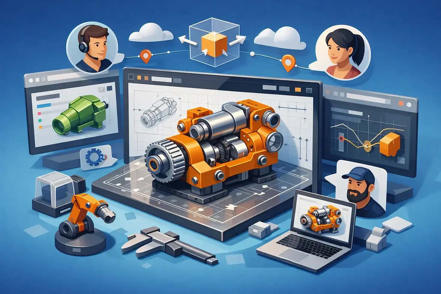
Autodesk Inventor Pro 3D Parametrics for Teams
A mounting bracket changes by 12 mm, a housing needs a different wall thickness, or a customer asks for a larger motor. In a drawing-led workflow, those changes can trigger hours of edits and checks. Autodesk Inventor Pro 3D Parametrics gives engineering teams a more controlled way to respond: define the design intent once, then allow related features, parts, and assemblies to update according to that intent.
For manufacturers and product development teams, the value is not simply a better-looking 3D model. It is the ability to make changes with fewer disconnected edits, produce more reliable documentation, and preserve the logic behind a design after it moves from one engineer to another.
What 3D parametrics means in Autodesk Inventor
A parametric model is built from rules, dimensions, constraints, and feature relationships. Instead of treating geometry as a collection of independent lines and surfaces, Autodesk Inventor records how the part was made. A sketch is constrained. An extrusion is tied to a dimension. A hole pattern references a face or work plane. A fillet follows edges created by an earlier feature.
This history matters when the design changes. If the bracket width increases, associated hole locations, flange lengths, and drawing views can update with it, provided those relationships were established correctly. The model is not just a shape. It is a structured representation of design decisions.
That distinction is particularly useful for teams producing configurable machinery, sheet metal components, jigs and fixtures, enclosures, fabricated frames, or families of similar products. These environments often involve controlled variation rather than completely new designs every time.
Autodesk Inventor Pro 3D Parametrics in daily work
The practical benefit of Autodesk Inventor Pro 3D Parametrics is change management at the model level. Engineers can set dimensions as parameters, name critical values, and use equations to relate one size to another. For example, an overall enclosure width can drive panel spacing, rail length, and the placement of mounting features. A material thickness parameter can influence bend-related sheet metal features and cutout clearances.
Parameters become more valuable when they represent meaningful engineering values rather than anonymous dimensions. Names such as `BaseWidth`, `MotorOffset`, or `PlateThickness` make models easier to review and safer to revise. They also help a team distinguish between a dimension that is intentionally fixed and one that should adapt when a parent feature changes.
At assembly level, constraints and joints define how components relate to each other. A shaft can remain concentric with a bearing, a fastener can remain aligned with a hole, and a guard can stay positioned relative to a machine frame. When changes are made at part level, the assembly reveals whether the revised design still fits, interferes, or requires a downstream adjustment.
The approach does have limits. Parametric modeling does not remove engineering judgment, nor will it repair weak design intent. A model filled with unnecessary external references, vague feature names, and conflicting constraints can become slow or difficult to edit. The objective is controlled flexibility, not making every dimension variable without a business reason.
Build design intent before adding detail
The strongest Inventor models usually begin with a short planning conversation. Before modeling, the designer should identify which dimensions are functional, which interfaces must not move, what may vary across product sizes, and which manufacturing rules control the design. This takes minutes and can prevent repeated rebuilding later.
Start with stable references
Use origin planes, work planes, axes, and clearly planned sketches as stable references for major features. Referencing a feature edge may be convenient, but it can create a fragile dependency if that edge changes or disappears in a later revision. Stable reference geometry provides a more reliable foundation for families of parts and long-lived designs.
A base feature should represent the core form of the part. Secondary features such as holes, pockets, ribs, chamfers, and cosmetic details should follow a logical order. This makes the model tree easier to understand during troubleshooting or handover.
Fully constrain functional sketches
A sketch should communicate more than shape. Constraints establish position, orientation, symmetry, tangency, and dimensional control. Fully constraining a functional sketch reduces accidental movement and makes the intended behavior clear when dimensions are edited.
Not every sketch needs excessive complexity. A simple, well-constrained master sketch is often preferable to one large sketch attempting to control every downstream detail. Where appropriate, separate sketches and work features keep complex models more manageable.
Use parameters to standardize variation
Named parameters are especially useful for repeatable products. They support standard sizes, approved clearances, and consistent design rules across a product range. An engineering manager can also create a review process around key parameters, ensuring that changes to safety-related spacing, material thickness, or load-bearing geometry receive the right level of approval.
For highly repetitive variants, iParts, iAssemblies, configuration approaches, or rule-based automation may be worth considering. The right method depends on how frequently variants are produced and how much they differ. A small range of simple sizes may only need a parameter table. A large product family with options, compatibility rules, and documentation requirements may justify a more formal configuration strategy.
Where teams gain measurable value
Parametric workflows improve efficiency when they are paired with disciplined processes. The clearest gains often appear in engineering change orders. Rather than manually updating a part, assembly, drawing, and bill of materials as separate tasks, teams can make a controlled model revision and review the resulting updates.
Documentation is another major benefit. Associative drawings can reflect model changes, reducing the risk of a released drawing showing dimensions that no longer match the manufactured part. This does not replace checking. Engineers must still review tolerances, notes, title block information, revision status, and any dimensions intentionally overridden for manufacturing communication. It does reduce the number of places where an inconsistency can begin.
Manufacturing coordination also improves when the 3D model contains accurate material, component, and assembly information. Sheet metal flat patterns, part properties, interference checks, and bills of materials can support better communication between design, purchasing, fabrication, and assembly teams. The result is not automatic error prevention, but a clearer shared source of information.
For organizations handling client-driven customization, this can shorten response time. A sales or project team can ask engineering for a revised capacity, footprint, or mounting arrangement without assuming the entire design must be redrawn. The engineer can assess the parameterized model, identify where the change propagates, and make an informed decision about cost and lead time.
Common implementation mistakes
The first mistake is treating 3D CAD as a direct replacement for 2D drafting while keeping the same habits. Sketching every profile without constraints, using arbitrary references, or manually typing dimensions into drawings after a model change reduces the value of the system.
The second is overengineering the model. Complex rules and deeply linked references can make a simple part difficult to maintain. Build automation only where the same decision repeats often enough to justify it. A one-off prototype may need a clean, editable model more than a sophisticated configuration framework.
The third is assuming software access equals team capability. Engineers and drafters need consistent conventions for file naming, templates, parameters, materials, drawing standards, and revision control. Without these foundations, even capable users can produce files that are hard for colleagues to reuse.
Training turns software investment into operational value
Effective Inventor training should be tied to the work a team actually performs. A designer creating sheet metal electrical enclosures needs different emphasis from a mechanical engineer building machine assemblies or a toolroom team producing fixtures. Generic feature knowledge is useful, but project-based practice is what teaches users how to structure models for reliable future changes.
A practical rollout typically combines core modeling skills with agreed company standards. Teams should learn how to create constrained sketches, manage parameters, build assemblies, generate drawings, and check revisions. They should also apply those practices to representative parts and assemblies from their own operation.
BLY Technology supports organizations that need more than software procurement. By combining engineering software access, technical training, implementation guidance, and ongoing support, the focus stays on helping teams use their tools effectively in real design and manufacturing work.
The best next step is to select one recurring product or assembly, model it with clear design intent, and test a realistic change request before broadening the workflow. That small exercise will show where Autodesk Inventor can save time, where internal standards need improvement, and where focused training will produce the strongest return.


Comments